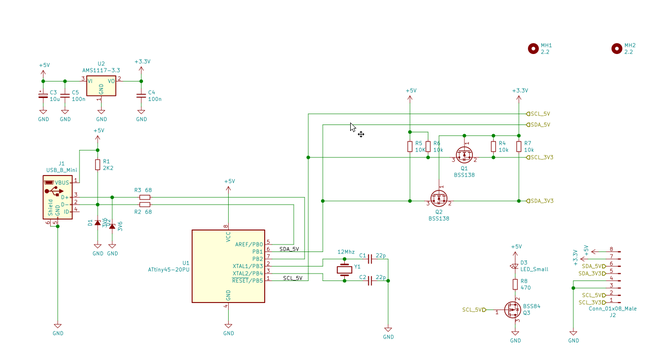
The operation is straightforward, the USB interface and the microcontroller circuit is the original, the level shifter is the classic Philips/NXP application note solution (see: https://www.nxp.com/docs/en/application-note/AN10441.pdf, and I added a switching FET for the LED on the SCL line, so the i2c line activity is indicated.
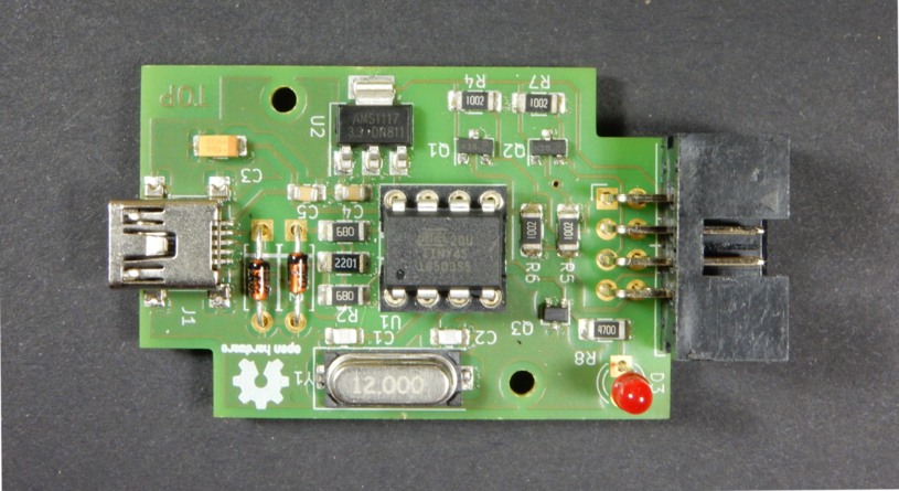
The PCB is designed in Kicad, although it’s double-sided, as the SMD parts are 1206, and there is only one via, it’s possible to build it on a DIY PCB as well. I got my PCB fabricated at Aisler, but as you can see on the cover image, I also made a prototype myself.The fabricated, populated board looks like this:
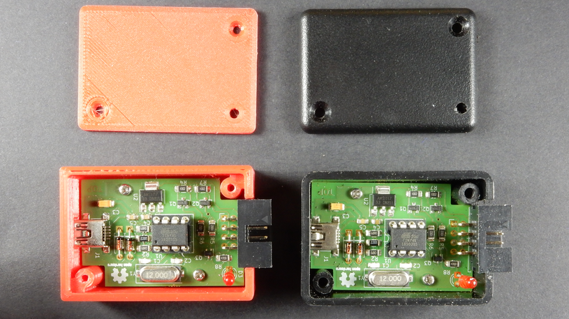
The board is designed to fit into the HM-1551GBK Hammond box, but I’ve also designed a 3D printable enclosure, see in the “enclosure” directory in the git repo and on Thingiverse: https://www.thingiverse.com/thing:4261556. This is how the boards look like in these enclosures:
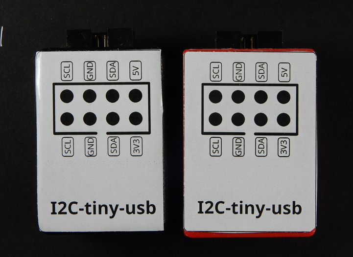
As a bonus, I also made a simple label with the pinout to stick it on the
enclosure:
The Kicad project available in the original i2c-tiny-usb repo at https://github.com/harbaum/I2C-Tiny-USB/tree/master/pcb/i2c-tiny-usb integrated with this pull request, so feel free to build it as it is, or redesign the layout based on the Kicad project.
]]>I decided to design this when I was starting prototyping an other project, and wished I had something similar. After a quick, unsuccessful query on Tindie (this is something similar, but not designed for breadboard, and not OSHW), the next thing I noticed was that I have Kicad open and I’m laying out this board. It’s nothing groundbreaking, but as you can see on the pictures, it’s directly pluggable into breadboard, and it can also power your breadboard circuit from the USB port, so I’m sure it can come handy sometimes to everyone on Earth. The schematic is pretty much the default design for the CH340G chip, plus there is some ESD protection on the USB line (USBLC6-2SC6), a 3.3V regulator with jumpers to select the output VCC and the UART line voltage and of course some LEDs for power and the TX/RX lines, as blinking LEDs are mandatory for any reasonable gadget.
The PCB is designed with Kicad, it’s double sided, but possible to build it on single-sided board as well. You can find all of the CAD files and documentation over at Gitlab (Github mirror), so here I just show a teaser:
The usage it’s pretty straightforward: just plug it into your breadboard, connect the UART lines to your circuit, select the operating voltage with the jumper, and connect the USB cable to your PC. If you are using any {r,d}ecent Linux distribution, the CH340G driver most likely is installed on your machine. If you are on Windows, you have to click around a bit, see for example the tutorial at Sparkfun]]>