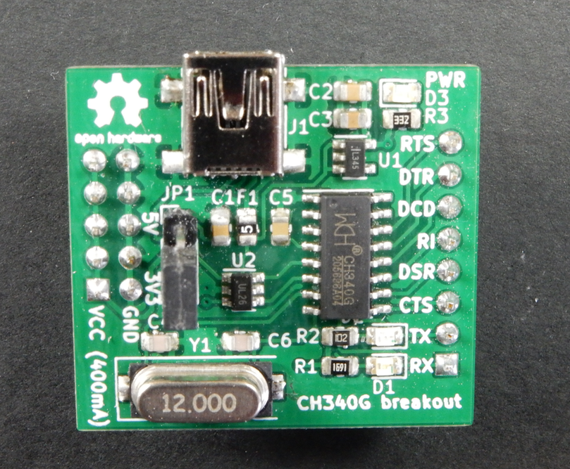
This a simple CH340G breakout board design, for using (mainly) on breadboards. There are a dozen of good designs out there, but this one tries to differentiate itself by being breadboard-friendly (meaning it’s possible to plug it into your board without sticking out vertically), provides (fused) power supply directly to the power rails of the breadboard (selectable 5V or 3V3), and it exposes all of the modem control lines.
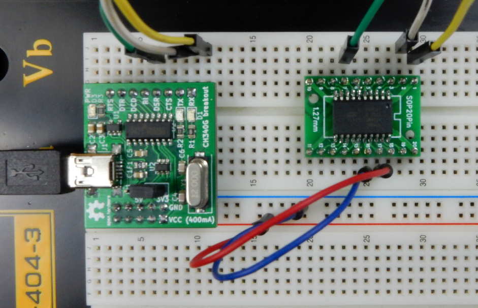
I decided to design this when I was starting prototyping an other project, and wished I had something similar. After a quick, unsuccessful query on Tindie (this is something similar, but not designed for breadboard, and not OSHW), the next thing I noticed was that I have Kicad open and I’m laying out this board. It’s nothing groundbreaking, but as you can see on the pictures, it’s directly pluggable into breadboard, and it can also power your breadboard circuit from the USB port, so I’m sure it can come handy sometimes to everyone on Earth. The schematic is pretty much the default design for the CH340G chip, plus there is some ESD protection on the USB line (USBLC6-2SC6), a 3.3V regulator with jumpers to select the output VCC and the UART line voltage and of course some LEDs for power and the TX/RX lines, as blinking LEDs are mandatory for any reasonable gadget.
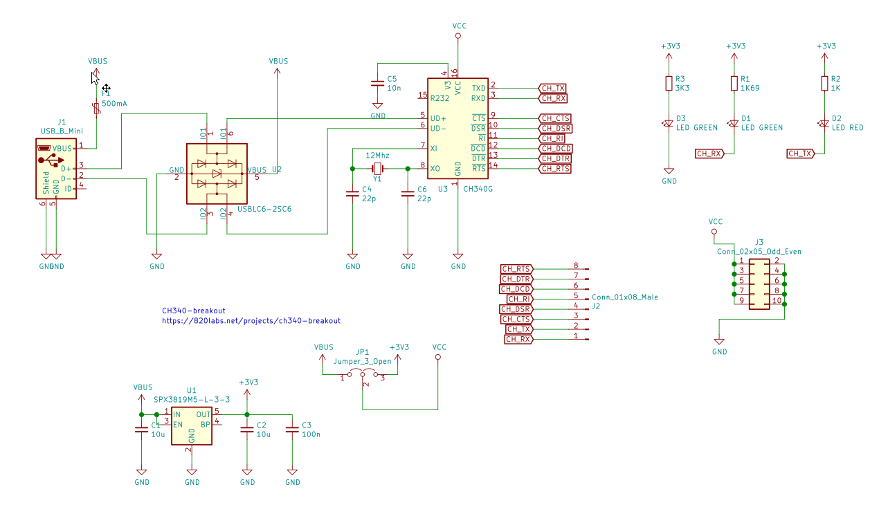
The PCB is designed with Kicad, it’s double sided, but possible to build it on single-sided board as well. You can find all of the CAD files and documentation over at Gitlab (Github mirror), so here I just show a teaser: